Friday, May 6, 2011

Step1: Creating Classes for UML Diagrams with their attributes and operations(return type and parameters)


Creating Classes
            Creating Classes is the very important step in creating UML diagrams. This is because it exponentially reduces the time you would require to model your diagrams. Study your problem statement and analyze it thoroughly. Identify the Classes . . .

There are 4 ways of identifying classes:

 1. Noun Phrase Method

         In this method you have to identify each and every noun in the problem statement and checklist it. Then try to eliminate them on the basis that they cannot become fully fledged classes; they are better as attributes of classes or that they are not required at all.

2. CRC - Class Responsibility Collaboration
         In this method you draw a CRC as shown below. This would help you to determine the functions of the Classes and other Classes that are connected to this Class. 


 The left Column consist of the Class’ member functions and attributes and the right column consists of its relationships with other columns.
3. Use Case Driven
         In this method you are expected to identify classes from use case scenarios. But in this case you will need to identify the scenarios first, which we will learn when we will see how to prepare a Use-Case Diagram.

4.Common Class Pattern Approach  
        This approach asks you to define Classes with fixed and universal functionalities. E.g. an ATM system Class in Banking Application. Various other patterns that may be defined are: Organization Class, People and Person, Devices, Places, etc.

 The best and relatively simpler approach to identifying classes, we would suggest, is the ‘Noun Phrase Approach’.

 Assuming that you have identified your Classes for your Problem Statement we should now see how to create a Class in Rational Rose, how to define its attributes, operations and functions, arguments and parameters, return type and relations with other Classes.


Thursday, May 5, 2011

Starting with UML Diagrams


         The Unified Modeling Language (UML) is used to specify, visualize, modify, construct and document the artifacts of an object-oriented software-intensive system under development. UML offers a standard way to visualize a system's architectural blueprints, including elements such as:

1. Activities
2. Actors
3. Business Processes
4. Database Schemas
5. (Logical) Components
6. Programming Language Statements
7. Reusable Software Components
  

           UML combines techniques from data modeling (entity relationship diagrams), business modeling (work flows), object modeling, and component modeling. It can be used with all processes, throughout the software development life cycle, and across different implementation technologies.
We would like to give you a hierarchy of diagrams.

1. Structural diagrams
1.1. Profile Diagram
1.2. Class Diagram
1.3. Composite structure Diagram
1.4. Component Diagram
1.5. Deployment Diagram
1.6. Object Diagram
1.7. Package Diagram
 
2. Behavior Diagrams
2.1. Activity Diagram
2.2. Use case Diagram
2.3. State Machine Diagram
2.4. Interaction Diagram
2.4.1 Sequence Diagram
2.4.2 Communication Diagram
2.4.3 Interaction Overview Diagram
2.4.4 Timing Diagram


In next post we would see how to create a diagram

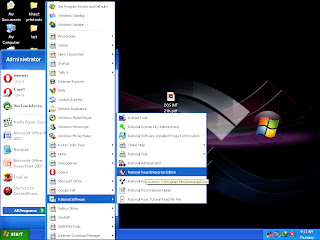
Starting with Rational Rose


Starting with Rational Rose.

Working with Rational Rose could be more fun if you know the basics right. Rational Rose is a software that provides many features other than just UML modeling. It helps to control the versions, generate code from your UML diagrams, and assign specific users to specific diagrams.
Descriptions and definitions of various features of Rational Rose is what you would find in abundance on the net, but this is more specific to what you are searching. Let’s see what to do with Rational Rose. . .


It is very important to select an appropriate model based on our project, programming language, and OS platform. A more generic model that can be used on various platforms is the ‘rational unified process’.


Selecting the model will give you the modeling window where you are expected to draw your diagrams.


Read next posts to learn more.